Experiment Operations During Apollo EVAs
Experiment: Laser Ranging Retroreflector
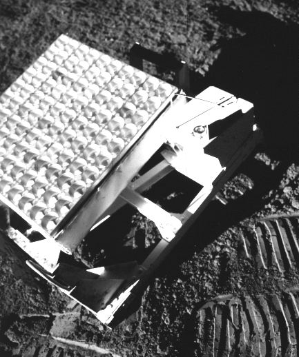
The LR3 as deployed at the Apollo 14 site. Note the bubble level and the shadow graph for orientation. These were set for the landing site location prior to launch (AS-14-67-9385). See also a method of carrying the LR3.
PI/Engineer: James E. Faller, Wesleyan Univ.
Other Contacts: C. O. Alley, Univ. of Maryland
Apollo Flight Nos.: 11, 14, 15
Apollo Exp’t No. S 078
Discipline: Earth/Moon system
Weight: A-11 23.59 kg, A-14 20.41, A-15 36.20
Dimensions:
A-11: 29.2 cm x 68.6 x 66.0
A-14: 30.0 cm x 63.8 x 64.8
A-15: 30.0 cm x 69.5 x 64.8 (30.0 cm x 105.2 x 64.8 deployed)
Manufacturer: Bendix
Description/Purpose:
An optical corner reflector to measure lunar librations (both in latitude and longitude), the recession of the moon from the Earth due to tidal dissipation, and the irregular motion of the Earth, including the Chandler wobble of the poles. This is accomplished by using the technique of short-pulse laser ranging. The LRRR of A-14 differed in only main design aspects from that on A-11. The LRRR on A-15 was the largest, with 300 separate sub-reflectors – The previous two had only 100. The A-15 array consisted of a hinged, two panel assembly (204 and 94 reflectors) mounted on a leg assembly, which was deployed by the astronaut. The larger array was to allow smaller telescopes on Earth to receive signals from it, but a report on 31 July, 1971 showed that the larger array was comparable, but not superior, to the smaller arrays.
Unloading from the LM: no comments by crew.
Transporting by foot or MET:
Carried by hand on A-11 to balance the PSEP package in the other hand. Also carried by hand on A-14 while pulling the MET.
Loading/unloading tools/exp’ts on LRV:
On A-15 it was carried on the LMP’s seat of LRV, held in place with the seat belt, and driven to the deployment site. The LMP was carrying the ALSEP at the time.
Site selection:
Generally flat and level area, 300 to 500 feet due W of the LM. Greater than 500 feet was requested to minimize the dust from LM ascent.
Deploying experiment:
Carried by hand (along with the PSEP on A-11) to the deployment site. The leveling leg, deployed by the astronaut by pulling a pin, provided the proper elevation angle for each site. It was tilted and then rested on the surface using the UHT. It was pointed towards the Earth. The bubble used to level the device on A-11 showed it to be within 0.5 degree of level, with the bubble oriented to the SW. A sun-compass allowed azimuthal alignment of the array with respect to the sun. After these steps, the dust cover was removed. There was no trouble deploying the A-14 or 15 LRRR, either. The operations sequence on A-15 was slightly different, but essentially the same tasks were performed. A typical timeline from A-15 shows ~6 minutes for deploying the experiment.
Check-out of experiment:
Range measurements to the A-14 LRRR (from Earth) were successfully accomplished on the day it was deployed. Measurements taken after LM liftoff indicate that the ascent stage engine burn caused no serious degradation of the LRRR reflective properties.
Operation of experiment: None, it is passive.
Repairs to experiment: NA
Recovery/take-down of experiment: NA
Stowing experiment for return: NA
Loading/unloading samples on LRV: NA
Loading of exp’t/samples into the LM: NA
Stowing of package once in the LM: NA
Sampling operations – soil, rocks: NA
Raking: NA
Drilling: NA
Coring: NA
Navigating/recognizing landmarks: NA
Were there any hazards in the experiment?
i.e. hazardous materials (explosive, radioactive, toxic), sharp objects, high voltages, massive, bulky, tripping hazards, temperatures? No.
Was lighting a problem? NA
Were the results visible to the crew?
The unit had a gnomon and bubble leveling device for the astronaut to use during deployment. The results of the experiment were not visible to the crew.
Would you recommend any design changes?
The overall design for the A-14 and A-15 reflector arrays was similar to that for A-11 except that the half-angle taper of the reflector cavities was increased so as to increase the array optical efficiency 20 to 30 percent for off-axis Earth positions. The number of reflectors in the array was increased for A-15 to permit regular observations with simpler ground equipment.
Were any special tools required? UHT
Was the orientation of the experiment (i.e. horizontal/vertical) important? Difficult?
Very important, but not difficult. It was aimed at Earth and leveled to within 5deg. Alignment was reported by noting where the shadow was cast on index marks by the gnomon. These marks were set for a specific landing site and deployment date.
Was the experiment successful? Yes.
Were there related experiments on other flights?
A-11, 14, 15 all had LRRR. A French-Russian array was carried on Luna 17. Two LAGEOS satellites were launched by the Shuttle (into high orbits within the Van Allen belts?).
Where was it stored during flight?
On A-11 it was stored in LM Scientific Equipment Bay, Quad II. A-14 stored it in Quad I. A-15 in Quad III.
Were there any problems photographing the experiment? No.
What pre-launch and cruise req’ts were there?
power, thermal, late access, early recovery? None.
What was different between training and actual EVA? No comments by crew.
What problems were due to the suit rather than the experiment? No comments by crew.
Any experiences inside the LM of interest from the experiment/operations viewpoint? No.
References:
Preliminary Science Reports for A-11, 14, 15
Apollo Scientific Experiments Data Handbook, JSC-09166, NASA TM X-58131, August, 1974, In JSC History Office.
Apollo Program Summary Report, section 3.2.19 Laser Ranging Retroreflector Experi-ment, JCS-09423, April, 1975.
ALSEP Termination Report, NASA Reference Publication 1036, April, 1979.